

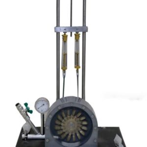
CENTRIFUGAL PUMP APPARATUS
S1-FM-109
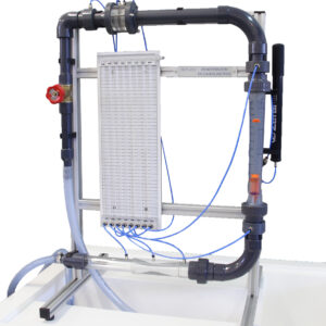
- Functioning of a surge chamber
- Pipe section with ball valve and surge chamber
- Surge chamber designed as transparent PMMA tank
- Pressure sensor behind the water chamber for measuring the pressure wave
- Pipe section with solenoid valve and two pressure sensors for measuring water hammer
- Volumetric flow measurement via measuring tank of the supply unit
- Representation of the pressure curves with software
- Flow rate determined by S1-FM-101 hydraulic bench
- Water supply using S1-FM-101 Hydraulic Bench or via laboratory supply
Description
The unit is composed by a centrifugal pump mounted on a basement and connected to a continuous circulation tank. The front part of the pump is in clear plastic to see inside. The suction and discharge pipes are transparent too and each one has a flow control valve. It has two interchangeable impellers, a forward curved impeller and a backward curved one, in order to compare their performances. The digital instruments allow to measure suction and discharge pressure to the pump, as well as flow rate and water temperature. The pump speed is accurately controlled by an industrial inverter within the interface console mod. Indicates torque and power consumption. The interface console mod. Data acquisition software to study the values of the parameters measured by the electronic instruments.
Specification
- Max flow rate: 1.6 liters per second
- Typical Max head: 9.0m
- Max pump speed: 1800rpm
- Motor power rating: 250W
Dimensions
- LxWxH: 900 x 500 x 500 mm


Leave a Reply